Bentley Rail Track |
  
|
Bentley Rail Track |
|
Introduction
The following information provides a brief outline of the "things to remember" when using the Plan Profile Generator.
Other information regarding Bentley Rail Track usage can be found on the Track Skills Network "Technical" pages.
Starting out
•Start Bentley Rail Track (BRT) (V08.09.02.16) from within MicroStation by selecting the following menus: CADtools > Applications > Inrail
•Load the relevant BRT information for your project (Note: Remember to select the appropriate Global Scale Factor)
•Start the Plan Profile Generator (PPG) by selecting the following menus: Drafting > Plan and Profile Generator
•Choose the correct preference file from the preferences button
•The Seed Host File requires a Mock border to be placed within it at 1:1 Scale and then the graphics deleted.
•The Mock border needs to be created as a .cel file with the same name.
The different tabs
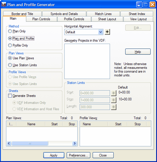
Main
•Make sure you have the correct horizontal alignment specified.
•Use Station Limits to create the initial sheet distances. From the Plan Views box you can change these distances to better suit your needs. With this option it is best to have Generate Sheets unticked and the Station Lock turned off.
•Use Plan Views for creating sheet drawings, with this option select the VDF Information and Host Files.
Plan Controls
•Ensure that the Force Rectangular Boundary option is selected.
•Using the Model Files button in the top right corner, select the appropriate files to be included as references. If you have mapping or aerial choose those references first or they may overshadow other references.
•Select the Nested Attachments options as appropriate.
Profile Controls
•The Seed View Name is only used by the PPG.
•The Margin spacing is based on the profiles, not the annotation and needs to take the scale factor into account.
•Select the appropriate Vertical Alignment from the drop down menu.
•Select the appropriate Surface's (Note: ensure that Default is also selected and that it is the only surface highlighted. This will allow the profiles to follow the alignment, not the surfaces which may have defects).
Sheet Layout
•Generate sheets in the Main tab has to be ticked on or this tab will appear greyed out.
•The Sheet Number is used in the matchline text to describe previous and next sheets.
•The Name is for information purposes only.
•Ensure that the Host File location is defined.
•Use the All Sheets in One option to create a Keyplan layout.
Symbols and Details
•Keys/Legends can be added using the ProjectWise Title Block section.
•All cells should be 1:1 scale and placed relative to bottom left of the border.
Direct link to this topic:
© 2013 Arup