Why Insert a “Mock Border”
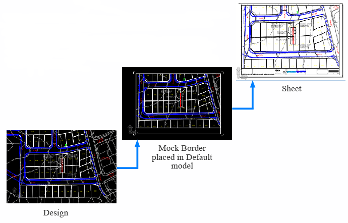
A “Mock Border” is inserted to determine the drawing area.
Anything that is to be displayed in the sheet when it is created should be placed within the “Mock Border”
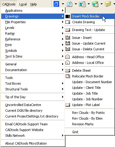
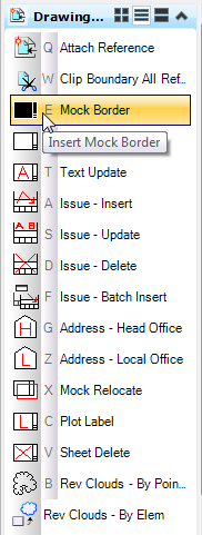
The “Insert Mock Border” tool can be started by selecting “Mock Border” from the CADtools> Drawings menu as shown below left or by selecting “Mock Border” from the “Drawing Setup” task menu as shown below right.
The CADtools ”InsertMock Border” tool allows you to select the outline, scale and orientation of the sheet. This “Mock Border” is used to give you an idea of the drawing layout, ie. what fits at the desired scale.
At this point the user may place a fence and clip back the references to the border.
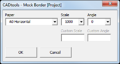
[Project] in the dialog box name indicates that drawing border configuration from project area is being used.
[Office] in the dialog box name indicates that the default drawing border configuration from P drive is being used.

Paper

Scale

Angle
Paper
A variety of predefined border sheets can be selected.
Note: The available border sheets may change depending on your project configuration.
Scale
The scale of the "Mock Border" can be selected from the drop down list of common scales.
Should the scale required not be available then "Custom" can be picked.
Angle
A rotation of the "Mock Border" can be selected from the drop down list of common angles.
should a non-orthogonal rotation be needed, custom can be selected.
Custom Scale
If Custom is selected from the Scale Drop down box then the Custom Scale input box gets activated and a Scale can be typed in.
Custom Angle
If Custom is selected from the Angle Drop down box then the Custom Angle input box gets activated and a Angle can be typed in.
When "OK" is clicked, the "Mock Border" will appear on the cursor and can be placed over the desired location.
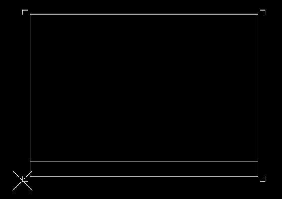
Once that is done all of the reference files can be clipped by placing a fence around the inside of the border and using the Reference Files>Clip Boundary ALL Files tool.
Key-in: vba run [CADTools_Drg_setup]Mock.Mock_Run
Direct link to this topic: