Setting up FloorManager |
  
|
Setting up FloorManager |
|
From within your 3D model, activate the Floor manager tools from “Triforma>Tools>Floor Management”.
|
|
|
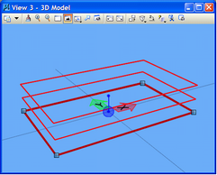
Click the right hand icon to open the ‘FloorMaster’ DGN file, this assumes the config variable “BB_FLOORMASTER_DGN” points to an appropriate file. The “Example-PCF.txt’ file delivered with CADtools Microstation contains appropriate definitions, if used with the Project Setup template as described in the CADtools Project Configuration manual.
Using the right hand icon to open the ‘FloorMaster’ DGN file will also open the ‘Floor Manager’ dialog box. The ‘FloorMaster’ DGN is readily identifiable by the blue window background.
|
|
|
|
|
|
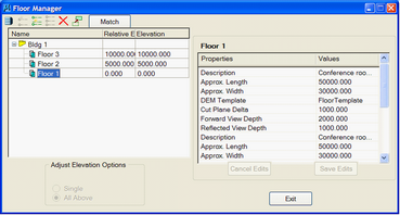
Using the Floor Mangement dialog box, create the levels for your structure, Ground , Level 1, Level 2 etc etc.. The levels can be defined using relative elevations (from an initial base level) or using absolute elevations.
When a Triforma model is opened the Floor Levels created will be available for activation for that particular model.
Each floor can also be given extra data such as approximate areas, and can be associated with a Drawing Extraction template. When associated with a DEM template, the ‘Cut plane delta’, and ‘Forward/Reflect view depth’ values will define the region used for drawing extraction. The ‘Building’ as whole can ge given non graphical data such as Address, Gross Volume etc. This data is later available through the Datagroup system (and in theory, is available when writing IFC files, or other data rich ‘BIM’ formats)
Direct link to this topic:
© 2013 Arup