A method of solving a drawing extraction which will not unify |
  
|
A method of solving a drawing extraction which will not unify |
|
Occasionally the drawing extraction process will produce results where the unification process has failed to unify properly, which can be caused by a couple of problematic elements in the model.
A typical drawing extraction will process the entire model at the location defined by the extraction cut plane, but the ‘Shape’ method of defining the cut location will restrict the area processed to a volume bounded by the shape. This is useful for narrowing down the area causing problems during extraction.
1. The desired extraction result (unification correctly processed)
2. An example of incomplete unification process.
3. Make a copy of the drawing extraction which is not processing properly.
Change the method of defining the cut location to be ‘Shape’.
4. Use a small shape area to define the extraction. Run the extraction, and if it unifies correctly, move the shape defining the extraction area around the model, until the extraction again fails. At that point the problematic elements lie within that shape.
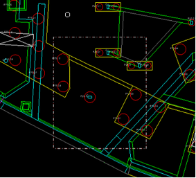
5. In this case, the cause was a mis-alignment between a column and recently added upstand which was trimmed to the column. This caused the unification process to fail.
6. Correctly aligning the elements is one way to fix the unification. This particular example can also be fixed by moving the cut plane upwards so it is above the top of the upstand. Note in the first image below, the cut plane (white chain-dot line) goes through the upstand. In the second image it is above the upstand.
Direct link to this topic:
© 2013 Arup