Co-ordinate Grid |
  
|
Co-ordinate Grid |
|
It will bring up the Place Grid Dialog box as shown below.
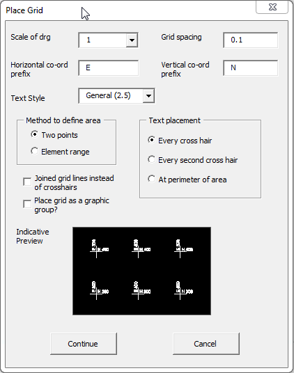
Scale of drg
Defaults to the model scale of the drawing, can be changed by selecting a scale from the preset drop down list of scales, the grid spacing will be scaled by the selected scale.
Grid Spacing
Sets the Grid Spacing for both the X & Y directions measured in master units of the file.
Horizontal Co-ord Prefix
Sets the Horizontal Prefix that will appear before the co-ordinates on each grid line.
Vertical Co-ord Prefix
Sets the Vertical Prefix.
TextStyle
Sets the textstyle to be used for the grid spacings from a predefined pull down list.
Method to Define area
•Two Ponts: places the grid inside a area defined by two points.
•Element Range: places the grid inside predefined rectangular shape by selecting the shape.
Text Placement
•Every cross hair: text is placed at every cross hair identifying its co-ordinate.
•Every second cross hair: text is placed at every second cross hair identifying its co-ordinate.
•At perimeter of area: text is only placed on the perimeter cross hairs identifying there co-ordinates.
Joined grid lines rather than cross hairs
Grid will have full lines in both directions to the perimiter of the grid, rather than just cross hairs at each grid co-ordinate.
This option only allows text to be placed on the co-ordinatyes around the perimiter or the grid.
Place Grid as graphic group
Grid is placed as a graphic group so that it can be moved or deleted as though it were a single element.
Indicative Preview
Shows a preview of what your grid will look like with the options that you have selected.
Direct link to this topic:
© 2013 Arup