Creating a cross section for placement as a GEO member |
  
|
Creating a cross section for placement as a GEO member |
|
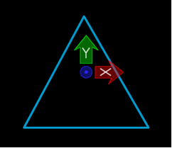
The first step in placing a GEO member is to draw the desired cross section. This cross section should be drawn as a shape, or complexshape element, which is made from only line or arc elements, and must be closed.
The shape should be drawn around 0,0,0, and must be drawn in the XY plane. The 0,0,0 will be used as the ‘origin’ of the cross section.
|
|
|
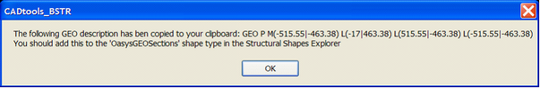
Once the shape is drawn, use the ‘Geo Desc from shape’ tool to generate a GEO description for that shape. Start the tool, then datapoint on the shape. If acceptable, the GEO description will be copied to the clipboard.
You should then open the Structural Shapes Explorer, and add a new ‘OasysGEOSection’ section to your available section sizes. Provide a suitable name, and paste the GEO description from the clipboard into the ‘Section Description’ field
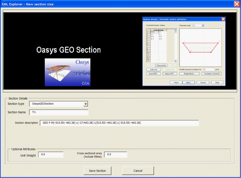
Save your changes in the Shapes Explorer, and exit the Shapes Explorer.
The shape drawn in the file can now be deleted.
Direct link to this topic:
© 2013 Arup