Placing GEO members |
  
|
Placing GEO members |
|
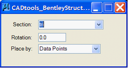
The ‘Place GEO member’ tools allows users to place members based on the sections available in the ‘OasysGEOSections’ part of the Shapes Explorer.
|
|
|
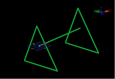
This tool works similar to the built-in Bentley tools, allowing the user to place GEO members by either end points, or along a path (or paths if a number of elements are selected).
Once placed the User3 and User4 datafields will be populated with the Section name, and Rotation (respectively).
|
|
|
|
|
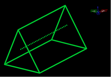
The resulting element placement |
Direct link to this topic:
© 2013 Arup