Drawing Setup Tools |
  
|
Drawing Setup Tools |
|
The CADtools “Drawing Setup Tools” are designed to to ensure that drawing sheets are created in a consistent manner, and adhere to the CAD standard relevant to that project.
This ensures consistent output of drawing files and printed output.
Contains Tools for automating repetitive tasks eg updating the “Drawing Sheet” & “TitleBlock”.
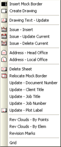
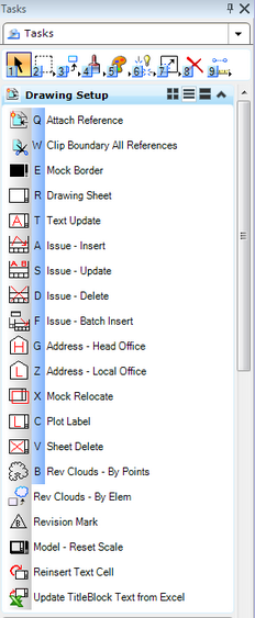
Selecting <CADtools> <Drawings> pull-down as shown below left or Drawing Setup tasks shown below right, gains access to tools which will automate the creation
of drawings; first, though, a word on Models and Sheets.
Models are where we assemble our design by putting together reference files; the sheet is
where the actual drawing is created with full drawing borders notes etc. MicroStation
design files can have many models and many sheets but the ARUP standard is to have
one model with one sheet. Drawing will have two models (design and sheet) and model
files will have one design model only.
![]()
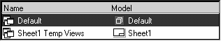
Models and sheets can be selected from the View Groups toolbox, although the Models
dialog box should be considered the location of choice for selecting models as
occasionally a View Group is not created when a model is made, if this happens then the
model name would not appear in the View Groups toolbox.
A sheet called Sheet1 will be created automatically for the user using the appropriate Drawing setup tools.
The drawing setup will automatically select either standard ARUP or Project Borders as appropriate.
Note: Configuration of projects is covered in a separate manual. If you are experiencing
problems, please seek the advice of your local CAD manager.
Direct link to this topic:
© 2013 Arup