Co-ordinates and the SWA |
  
|
Co-ordinates and the SWA |
|
The ‘Solids Working Area’ is a hang-over from previous versions of Microstation which had a limited ‘design area’. Indeed most CAD programs have a limited area within which their co-ordinate systems are accurate (this is related to the way numbers are stored by computers).
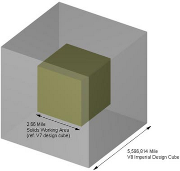
The ‘Design Cube’ is a 3d cube within which Microstation can store accurate co-ordinates. Using the ArupLib_3d_mm.dgn seed file, each side of this cube is about 900 Million kilometres long. Therefore, with the 0,0,0 at the centre of this cube, your largest X, Y, or Z co-ordinate (in mm) is about ±450,000,000,000, 000.
The ‘Solids Working Area’ is a much smaller cube, which is always at the centre of ‘Design Cube’ within which Microstation can store accurate information about solid elements. Using the ArupLib_3d_mm.dgn seed file, the each side of the SWA is 429 kilometres long. Therefore the largest X, Y, or Z co-ordinate (in mm) is about ±214,500,000. And since many national map grids cover area greater than 429 kilometres, this means that some real-world co-ordinates lie outside the SWA.
|
|
|
To test if your project will be modelling inside the SWA, simply draw some graphics in their rea-world co-ordinates, and then keyin “mdl load swa”. This MDL application will draw cube of the boundary of the Solid Working Area. If your graphics lie completely inside this cube, then your project lies within the default Solids Working Area. “mdl unload swa” will get rid of the cube drawn by the MDL application.
If your project lies outside the SWA, read the following section on how to move it so it is inside the SWA.
Direct link to this topic:
© 2013 Arup