Creating 3D PDF’s |
  
|
Creating 3D PDF’s |
|
The Adobe and Bentley alliance has given us the ability to create 3D PDF’s which enable anyone who has Adobe Reader version 7 or greater to navigate and fly around a 3D model created in Microstation. They are easy to generate and if you follow a few simple rules outlined below then you will get consistent results which will make navigation easier.
Below is the print dialog box brought up from CADtools > Plotting > PDF Adobe + Colour
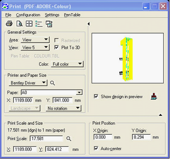
Tick the Plot To 3D box and choose the view you wish to print from. It is recommended that this view should be a saved camera view. Saved views will available in the 3D PDF file so we recommend creating lots of saved camera views as this makes the navigation much easier.
The “Active Depth” should be set for each saved view as the point you wish to rotate around in the 3D PDF view.
Tip: For any floor level that you wish to “Walk” around, the camera should be set up at eye level looking straight forward and then save the view with a name that describes the view, e.g. “Level 2 lobby”.
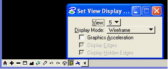
The camera view should be set to wireframe with no graphics acceleration see below.
The recommended 3D Plotting Options which are accessed from the Print dialog box under Settings > 3D plotting are shown below.
|
|
|
You can include layer information by ticking the “Include Standard PDF Data” tick box but this is not recommended for models created with Structural, Architectual or HVAC components as the file size will be large and in some instances corrupted.
Layers can be displayed off from within the 3D PDF by “Selecting” them and then “Hiding” them. There is also the ability to select by individual element or by it’s material property. This is accessed by right clicking anywhere in the view and selecting the desired selection method and selection render option.
The “Display Mode” is best set to either “Shaded” or “Shaded Illustration” but can be changed from within the 3D PDF by right clicking anywhere in the view and selecting the desired scene render option.
The “Background Colour” is personal preference and as above can be changed from within the 3D PDF.
You may wish to experiment with some of the other options but we have found this setup gives us the most consistent results.
Note: It has been noted that 3d PDF’s will fail to properly include elements created using ‘Plate Girders’ and will also ignore and bump-maps that are part of rendering assignments. ( Issues noted on Microstation v8.5.2.35 )
Direct link to this topic:
© 2013 Arup