Modelling concrete elements. |
  
|
Modelling concrete elements. |
|
A suggested way to model a 3d concrete structure is documented below, the benefits of modelling this way are:
•Maximise results of 2d drawing extraction (e.g. member labelling, dimensioning etc)
•Flexibility when multiple modellers are involved on one project.
•Adaptability to design changes
Note
The suggested methods below are possibly subject to change once future versions of Bentley Structural include better ‘DataGroup’ functionality.
Element: Vertical elements like Piles, Columns or Pad Footings.
Method: Select the appropriate cross-section from the Structural Shapes XML file (or create a new section size), place the element by 2 points using the ‘Place Concrete Column’ tool.
Reason: This allows the resymbolisation rules to work on elements like Pad footings, and produce appropriate annotation
Element: Concrete Ramps
Method: Feature modelling.
1.Place profile of ramp as a shape.
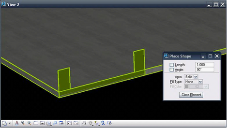
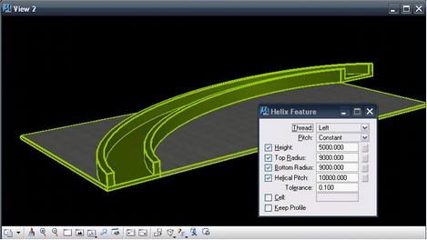
2.Use the Helix Feature command from the Profile Feature Solids toolbar.

3.Fill in the Height, Radii, Pitch and follow the prompts
4.Define the bottom radius (or direction if you provided value)
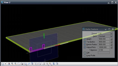
5.Define height (or direction only) and Top radius (or direction only)
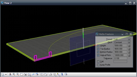
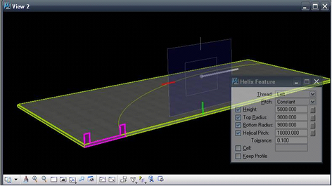
6.Accept preview.
Reason: This allows for the ramp to be modified with reasonable ease.
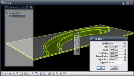
1.Select ‘Modify’ from the Feature Solids manager (?)
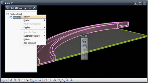
2.Modify the appropriate values
Element: A
Method: A
Reason: A
Direct link to this topic:
© 2013 Arup