CADtools Ustn 2.2 release notes |
  
|
CADtools Ustn 2.2 release notes |
|
The following items should be attended to as part of your upgrade to the CADtools Microstation 2.2 release:
You may need to update your DomainSettings.txt file to include the 'OfficeDetails' section, Refer to Changes_to_DomainSettings.txt_and_ProjectSettings.txt section below
Any projects running under Microstation XM, with a project specific address in the Project Config File (PCF) must now define that address in the ProjectSettings.txt file. Refer to Changes_to_DomainSettings.txt_and_ProjectSettings.txt section below
The Microstation XM and v8 2004 versions supported have not been changed, but the Bentley Structural and InRoads XM versions have been updated, you are strongly advised to upgrade to these versions. Refer to Supported_software_versions
Changes to DomainSettings.txt and ProjectSettings.txt
To further increase the compatibility of the CADtools products, some changes have been made to the way CADtools Microstation will read the office and any project specific addresses. For a complete discussion of how the DomainSettings.txt and Projectsettings.txt file format define the address, refer to DomainSettings.txt_and_ProjectSettings.txt Address_Details
CADtools Microstation running under Microstation XM now supports the same Local Office address definition as those used by CADtools for AutoCAD 2.1. i.e the 'OfficeDetails' section of either ProjectSettings.txt or DomainSettings.txt. Office addresses defined by either CADtools_Local.cfg or the PCF file are no longer supported. The sample DomainSettings.txt and ProjectSettings.txt distributed with CADtools for Microstation have been updated as appropriate.
Assumptions/process as follows:
1) Changes only affect Microstation XM (not v8 2004)
2) Any local addresses (_Cbs_Address_L1 to _Cbs_Address_L4) defined in CADtools_Local.cfg or PCF files are now ignored
3) The local address is always read from DomainSettings.txt.
3a) If the 'OfficeDetails' section is found, it will be used
3b) If 'OfficeDetails' is NOT found, 'Address' will be used and a warning message will appear in the MessageCentre
3c) The corresponding OFFICEDETAILS[n] or ADDRESS[n] titleblock tag mapping will be used (i.e it won't read address from OfficeDetails but map tags based on ADDRESS[n]
4) When ProjectSettings.txt is read, any addresses defined in an OfficeDetails section will overwrite those determined from DomainSettings.txt
4a) If the ProjectSettings.txt 'TitleBlocks' section contains tag rempappings based on OFFICEDETAILS[n] these will be used.
4b) If OFFICEDETAILS[n] is not found in ProjectSettings.txt, CADtools Microstation will read the ADDRESS[n] titleblock tag mapping if available. At this time, no warning will be issued to the user, but a 'Debug' message will appear in the MessageCentre if debugging is enabled.
So, in short OfficeDetails{ } and OFFICEDETAILS[n] are now the preferred ways to define address values and the relevant title block tags in either DomainSettings.txt or ProjectSettings.txt
'Address{ }' is still supported as a fall-back in DomainSettings.txt ADDRESS[n] as a title block tag remapping is still supported as a fall-back in ProjectSettings.txt. (Previously CADtools ustn didn't read title block remapping from DomainSettings)
For more information refer to these notes presented at the Arup CAD Conference Media:CADtools_Ustn_2.2_Notes.pdf
Other items fixed/added
You can see the list of items that are scheduled for the CADtools Microstation 2.2 release here: Bugzilla list CADtools 2.2 for Microstation
Of note are the following items from that list:
•Batch Update Drawing Status.
•User must first run the keyin "vba run [CADtools_Drg_Setup]Tags.Set_Status_For_Batch_Update"
•Then use the 'Batch Process' command with the supplied 'CADtools_Drawing_Update_Status.txt' to run against a selection of DGN files with drawing sheets
•Batch Create drawings
•See this page CADtools_Ustn_Batch_Create_Drawings
•Updated Plot drivers for XM
•The device drivers have all been updated to use the latest .pltcfg file format (xml). This has allowed for both a unified plot driver file rather than multiple device specific drivers, and additional features previously unavailable through the .plt file format
•The standard device output will now be using the local windows device queues, this allows the local users to set features which are applicable to a specific machine i.e. Folding options, Page trim and rotate options etc... speak to your local IT for device set-up information.
•Debugging output
•Useful when problems arise such as with reading ProjectSettings.txt, inserting drawing borders etc. Refer to CADtools_Ustn_Enabling_Debugging
•Bentley Structural
•Supported version of Bentley Structural is updated to be the 08.09.04.54 version which includes the Bentley developed link with GSA
•Structural Shapes Explorer now warns before a section is deleted
•Long Border Files
•The long border files have been updated to include, additional lengths and the re-defined text styles. Lengths from 1440mm to 10080mm at 360mm intervals are now available. The files are stored in individual folders off the root of the '..\Settings\' folder on the local 'P' drive (P:\Program Files\Oasys\CADtools_Ustn\Common\Settings\Long Borders\**). (Note: Although stored in a seperate area on the office server, all border files are still required to be defined for a project from the same location as noted in the LocationPath in the DomainSettings.txt_and_ProjectSettings.txt#Title_Blocks file)
•Support for GenerativeComponents in CADtools
•This release includes support (and installer scripts) for running GenerativeComponents under the same Microstation installation as CADtools is running. Whilst the 'CADtools' menu is visible in GC, many of the command won't work (or make little sense). The Plot to 3d PDF option is of use though. Refer to CADtools_Ustn_GenerativeComponents for more information
•Batch re-insert drawing text cell
•Useful when the title blocks have been changed, after a number of sheets have been created, see this page CADtools_Ustn_Batch_Process.
•Seed file updates
•Text and Dimension style updates as per user requests/features have been amended in the ArupLib_**.dgn seedfiles.
•CAD Standards
•Pentable changes per user updates to the Arup CAD Standard, and increased compatability with CADtools AutoCAD.
•CadSN_Default.tbl and CadSN_WYSIWYG.tbl replacing previous pentables used.
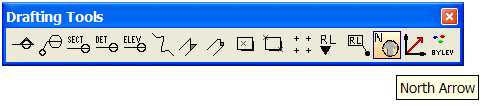
•North Arrow tool
•CADtools Microstation now includes a North Arrow tool in the 'Drafting Tools' task.
Supported software versions
The CADtools for Microstation 2.2 release is supported for the following product versions:
•Microstation: 8.9.4.51 (Unchanged)
•InRoads: 8.9.2.16 (Updated)
•Bentley Structural: 8.9.4.54 (Updated)
•Bentley Building Mechanical: 8.9.4.29 (Unchanged)
•Bentley Building Electrical: 8.9.4.10 (Unchanged)
•Bentley Building Architectural: 8.9.4.30 (Unchanged)
•GenerativeComponents: 8.9.5.43 (New)
•Bentley Redline: 8.9.4.51 (Unchanged)
Refer also to CADtools Ustn Software Versions
The CADtools Microstation team have been working with the Global IT team to make available the CADtools installers through the Systems Management Server (SMS) technology. This is Arup standard technology which allows IT admins to automatically deploy software to PC, reducing the burden of work to keep your CAD PC's up to date with the latest software.
Please see the CADtools_Ustn_SMS_Install page for more information.
In addition to the SMS installation, we also support the normal batch file installation, where possible these batch files will also now take care of un-installing any relevant previous versions of the software. These updated batch file installers live in P:\Program Files\Oasys\CADtools_Ustn\Local\Install\
•InRoads: 8.9.2.16 Updated - Run the \Local\Install\InRoads_v89.bat to install latest version, and also uninstall an previous 8.9 version
•Bentley Structural: 8.9.4.54 Updated - Run \Local\Install\CADtools_Structural_XM.bat to install latest, and also uninstall previous 8.9.4 versions of Structural and Triforma)
•GenerativeComponents: 8.9.5.43 New - Run \Local\Install\CADtools_GenerativeComponents_XM.bat to install latest GenerativeComponents and Triforma.
In some cases, you may need to remove the previous 8.9 (XM) versions of these programs, and then re-run the install script, if the installation fails. These batch files all work on the basis that CADtools Microstation XM has previously installed using the 'CADtools_Microstation_XM.bat' batch file in the same directory.
T
his release includes a number of 'Beta' tools available for users to test and provide feedback. As these tools are still in development they are not yet available through the GUI and should be used with caution.
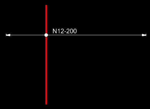
A tool used to draw indicative extent and layouts for reinforcement bars, post tensioning, steel/timber purlins or joists. The keyin required to run this tool is:
vba run [cadtools_structural_tools]tools.multibar
Typical output of the tool is similar to the following (depending on the options selected):
Batch replacement of Bentley Structural member section sizes
This tool will replace all instances of a Bentley Structural member of a given size, with a new member of a different section size. For example the following keyin
vba run [cadtools_triforma_structural]tools.batchupdatestructuralsection 150X100X5.0 RHS, CHS273.1X9.3
would replace all members of the size "150X100X5.0 RHS" with a member using the "CHS273.1X9.3" size
These tool will attempt to modify either the 'placement point' or the 'offset' of a Bentley Structural member, without changing the member's physical location. This is useful for removing offsets or changing placement points before export to formats such as SDNF where those features have been known to cause problems. These tools are activated by the following keyin commands:
vba run [cadtools_triforma_structural]tools.removememberoffsets
and
vba run [cadtools_triforma_structural]tools.changeplacementpoints
If you have a selection set before you run the tool, it will only process the selection set. Warning the results of this tool may be inaccurate when run against BSTR members along a curved path. If the curved opath is non-planar, the tool will not attempt any changes at all.
Direct link to this topic:
© 2013 Arup