The 2.4 release of CADtools Microstation includes initial support for Microstation v8i and some of the related design applications commonly used by Arup (e.g. InRoads, Structural Modeller, GenerativeComponents)
A future CADtools Microstation release will add support for the v8i versions of Bentley Architecture, ProjectWise Navigator, Bentley Building Mechanical Systems and Bentley Building Electrical Systems
At this stage CADtools 2.4 does NOT add any new features or workflows that support some of the new Bentley features such as 'Drawing Views'. Hopefully you will find that these features work, but CADtools will not integrate with them yet.
This was a concious decision based on getting v8i into your hands, so you can help us explore and understand how these tools might fit into the CADtools workflows. Feedback about these new Bentley tools can be sent to CADtools Microstation Support or CADtools Bentley Structural Support
The installers for supported v8i products are located at P:\Program Files\Oasys\CADtools_USTN\Local\Install\
CADtools Ustn SMS Install for 'push deployment' will also be available soon.
Based on feedback from CAD managers, this CADtools release provides a way for CAD managers to define which version of Microstation should be used on a specific project by adding some data to the Project Configuration File.
The system aims to be backwards compatible without editing existing v8 2004 or XM project configuration files. For v8i the required data must be defined within in the relevant PCF file.
Refer to defining the Microstation version for a project for further explanation.
The CADtools PDF drivers now offer the ability to create PDF's at differing resolution, so you can select an appropriate resolution to control the resulting PDF file size if desired.
The suggested default resolution is 300 DPI.
Note for CAD managers: In order to achieve this, the previous PDF plot drivers will be removed from the local P: drive. If you had project or office specific menus pointing to these particular driver files, you may find they no longer work
•P:\Program Files\Oasys\CADtools_USTN\Common\pltcfg\v8.9\cadtools_+pdf.pltcfg
•P:\Program Files\Oasys\CADtools_USTN\Common\pltcfg\v8.9\cadtools_-pdf.pltcfg
The introduction of the use of ModelScale to control Linestyle scale in CADtools Microstation XM has caused problems for some users.
The problem affects linestyles that have been created to represent real world items at their actual size, for example:
•Highway linemarkings - Dashes must be a real world length, not plotted length
•Linestyles that represent pipe work, and therefore have a real world width.
The following notes have been produced to assist with solving these problems.
CADtools Ustn - Producing drawings using "actual size" linestyles aka "highway linemarking"
CADtools Ustn - Producing drawings for with text at multiple scales
Added two new items to the 'Batch Proccesses' task/menu
•Detach all references that are turned off. (Useful for cleaning up DGN's before issue)
•Batch Update Drawing Titles (Useful for changing Drawing Titles en-masse)

The following default settings are applied when attaching a reference file (note, these can be overridden by the user)
•Attachment Method = Coincident world (so global origins align)
•Display = On
•Snap = On
•Locate = Off (A bit controversial, but it's the safest setting, and can be overridden)
•Treat as element = Off
•Save Relative Path = On (This should not affect any references attached using config variables)
•Display raster refs = On
•Scale LineStyles = Off (Scaling of linestyles should only be necessary when the reference attachment is not 1:1)
•Amended the MS_CELLLIST path, to resolve issues regarding the inability to use the 'File > Attach' menu in the Cells dialog.
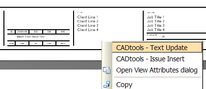
•The right click menu in a 'Sheet model' contains shortcuts to relevant CADtools commands.

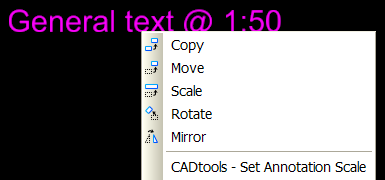
•The right click menu of a text or dimension element contains command to change annotation scale

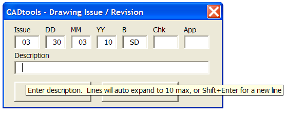
•Shift+Enter creates a new line in the Insert Issue dialog box

1) Create your project folder structure if one doesn't exist.
•Depending on your local work instructions you can use the template folders in P:\Program Files\Oasys\CADtools_USTN\Columbus\4-03 Drawings
2) Setup a ProjectSettings.txt file in the job folder.
•Copy P:\Program Files\Oasys\CADtools_USTN\Common\Columbus\ProjectSettings_XM.txt to your job area and rename to ProjectSettings.txt (Note: Although the file is called ProjectSettings_XM.txt it should still be used for v8i projects).
•For the Australian Borders Copy P:\Program Files\Oasys\CADtools_USTN\Common\Columbus\Aus_ProjectSettings_XM.txt to your job area and rename to ProjectSettings.txt
•Depending on your local work instructions, the ProjectSettings.txt usually exists in the top-level project folder, and has a 'Settings' folder next to it.
•You may also wish to use the new CADtools ProjectWizard which includes a template ProjectSettings.txt suitable for CADtools Ustn
3) If required, setup a Project Workspace (PCF)
a) Copying the Example_PCF.txt file
•Copy P:\Program Files\Oasys\CADtools_USTN\Common\Columbus\Example_PCF.txt to P:\Program Files\Oasys\CADtools_USTN\Projects\ and rename it to your project job number
•For Australian Settings Copy P:\Program Files\Oasys\CADtools_USTN\project\templates\Aus_Example_PCF_V8i.pcf to P:\Program Files\Oasys\CADtools_USTN\Projects\ and rename it to your project job number
b) Edit your new Project Workspace (PCF)
•The updated Example PCF contains a 'Mandatory Settings' section and an 'Optional Settings' section.
•The 'Mandatory Settings' contains three configuration variables for defining the project location. _PROJECT_DRIVE, _PROJECT_PATH, _PROJECT_PATH_DRGS. These are the same as previous CADtools releases
•The 'Mandatory Setting's also contain two new variables CADTOOLS_PROJECT_USTN_VERSION and CADTOOLS_PROJECT_UNITS.
•The value of CADTOOLS_PROJECT_USTN_VERSION must be one of 'V82004', 'XM' or 'V8I'.
•The value of CADTOOLS_PROJECT_UNITS must be one of 'M', 'MM' or 'MMforM'.
•These new variables are used to control some CADtools behaviour, and also automatically select the correct Text/Dim/Linestyle libraries (previously manually configured)
When introducing support for Microstation v8i, the CADtools team have tried to minimise the amount of changes from projects supporting XM.
CAD managers are advised that the best course of action is to ensure that all project staff are using the same version of software, but the following information will assist when deciding how to roll out v8i.
Software in use |
Can use XM and v8i on same project ? |
One way upgrade from XM project to v8i project ? |
Microstation XM only |
Possibly (requires two PCF files) |
No changes to DGN file format, or CADtools data, so can be reversed by undoing changes to the PCF |
InRoads XM |
Very limited, not recommended |
ALG and DTM files have to be saved in new format; XIN file with minor changes; ITL and SDB files the same |
Bentley Structural XM |
No |
Yes. Data in the DGN files and the Rules files will be automatically upgraded if opened with Structural Modelller v8i |
The Example_PCF.txt has been updated to support v8i, but most of the settings remain the same and the underlying configuration files (TextStyles, DGNlib, layer libraries) have not changed.
The introduction of defining the Microstation version for a project means that to upgrade a current XM project to a v8i project, CAD managers will need to add a few lines to the existing PCF.
CADtools Ustn 2.4 - Upgrading Microstation projects from XM to v8i
ALG and DTM
•Both the ALG and DTM formats have changed. Saving back to XM is possible using the 'Save As' + [Option] button.
XIN
•The current Arup civil.xin file has been updated and now contains both: Highways ('CH_' prefix) and Drainage ('CD_' prefix) preferences.
•It is recommended to use the new (IR V8i SS1) civil.xin file on new projects as number of references have been changed in new version of InRoads (for example - 'View Stationing').
Note: The Arup version civil.xin that is installed for use with InRoads XM has not been changed with this release
Design Standards
•New Arup Design Standards seed contains number of roads and highways standards: DMRB (UK), MTQ (CAN), AASHTO (USA) and Dz.U. (PL) Design Standards are available via 'Item browser'
Context menu
New InRoads task menu contains:
•Active Geometry
•Update 3D/Plan Surface SDisplay
•(tracking) Horizontal Alignment
•(tracking) Vertical Alignment
•New Geometry Tools
•InRoads menu
•Roundabout menu
•Civil AccuDraw menu
•Global Scale Factor
Structural Modeller (was Bentley Structural) projects
In addition to the changes required to upgrade a Microstation XM PCF to one suitable for Microstation v8i ([see above]), a number of other minor changes are required to get Structural Modeller v8i to work with project configuration files (PCF's) originally created for Bentley Structural XM. If you don't make these changes, you will encounter a number of non-fatal warning messages when starting Structural Modeller v8i.
Note: Using BSTR XM and Structural Modeller v8i on the same project is NOT advised, i.e if upgrading a project to v8i, all people on that project must use Structural Modeller v8i.
This is because Structural modeller will silently upgrade the format of the resymbolisation rules file (<Settings>\CADtools_Ustn\Triforma\stf_si\rules\stfDrawings.rul)
CADtools Ustn 2.4 - Upgrading BSTR projects from XM to v8i
Supported Software versions
CADtools Microstation supports v8 2004, XM and v8i series products.
The supported versions of the v8 2004 and XM products has not changed. The supported v8i product versions are as follows:
•Microstation: 8.11.7.180 (Added)
•InRoads: 8.11.7.229 (Added)
•Bentley Structural: 8.11.7.61 (Added)
•GenerativeComponents: 8.11.7.66 (Added)
•Bentley Building Mechanical: 8.11.xx (Not yet supported)
•Bentley Building Electrical: 8.11.xx (Not yet supported)
•Bentley Building Architectural: 8.11.xx (Not yet supported)
•Bentley Redline: 8.11.xx (Not yet supported)
Refer to CADtools_Ustn_Software_Versions for the list of officially supported versions
Direct link to this topic:
© 2013 Arup